Creating new, user-defined measurement types
Each measurement is described by a set of parameters. Some of them are mandatory and must be present in each type definition. These are: File, Path and measurement Date. There are also other parameters that may be used to describe a measurement of a given type. A user defines the parameter set. It may consists of up to twenty floating point, double precision numbers, up to ten long integers, two Boolean parameters, two strings of up to 255 characters each, an additional date parameter and a text parameter of virtually unlimited length (~65000 characters).
There is a screen Measurement Types & Parameters called through the [View|Measurement Definition...] main menu command, which is used to inspect, modify and add new measurement types into the base.
The first item here is a type name.
Then there is a description field of up to 255 characters long.
Next you describe X and Y axis data: 'name' and 'unit' are obvious. 'name has to be provided, 'unit' may be left empty.
'column' describes position of relevant data in a row in [data] section of data file. If it is =0 then no data is provided. Columns in a [data] vector are numbered from 1. Value of 'column' for Y [column(Y)] may not be equal to 0, as at least this one data column has to be provided in a file. If column(X)=0 then X values has to be inferred from data row number. In such a case in [parameters] section there should be a set of parameters named 'Start', 'End' and 'Step' which provide data for computing X values on the fly.
'log scale' indicates, that default display mode of the corresponding diagram axis is as shown.
It is possible to define a default file location (use ".\" for current database folder) and file name extension (do not prepend it with a dot).
One starts by clicking New type button, fills the above mentioned fields and saves the new type using Save button.
After defining the new type user has to create a set of parameters which will be used to describe the measurement. For this purpose the Parameters section of the form is used. There is a list of defined parameters displayed, empty at first. After clicking the Edit params button a set of additional controls is shown below the parameter list. An example of the screen in parameter editing mode is shown below.
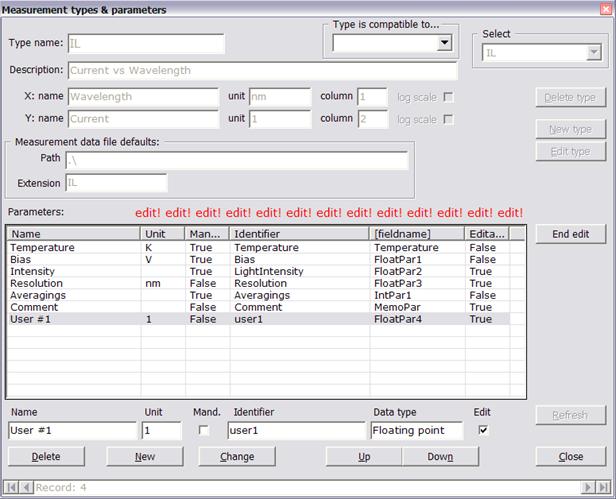
Text boxes and check boxes in the upper row correspond to columns of the list above them.
Name contains name of the parameter, i.e. text that will be displayed on lists and diagrams,
Unit is optional; if present it is appended to parameter name, enclosed in square brackets,
Mandatory when set indicates that the parameter field has to be present in measurement file, otherwise format error is reported,
Identifier is a string which identifies parameter in the measurement file, in section labelled [parameters]. The program uses it to retrieve data from measurement file while importing it into the base. Do not use non-ASCII and punctuation characters in this string,
Data type contains identifier of data type (in add-new mode it is a combo box) or specific, internal field name in the base; data type of existing measurement parameter may not be changed,
Edit when set indicates that the user defined parameter may be manually modified after storing measurement data in the base; almost all built-in parameters may not be modified, all user defined can be modified by default.
A set of buttons in the lower row of controls is used to add, edit and modify parameters. Order of parameters on the parameter list, and on all other lists throughout the program, may be changed using Up and Down buttons; this can be done for built-in parameters also.
User defined measurement types are usually used with data acquisition program which are not a part of Transient Processor System. Hence data files are also created by external programs. In order to enable data import from such files they should conform to rules listed below.
Data file should be divided into sections, each starting with a section name enclosed in square brackets. Each file has to consist of at least four sections listed below, together with mandatory parameters. Each section, excluding [data], may contain as many additional parameters as necessary. A file may contain additional data sections also. The [data] section should be the last one.
Basic data file format is as follows:
type=<user measurement type name>
material=<material identifier>
No measurements=<number of data rows in [data] section>
The [general] section has to contain entries specifying measurement type (type=) and measurement date (date=) in format shown. Time part is optional.
The [sample] section contains two mandatory entries material and identifier. They are used to assign measurement to appropriate sample in the database. All other entries are optional, although their values, if present, will be read and stored in the base. area is in mm2, capacitance in pF.
The [parameters] section has to contain at least No measurements parameter specifying number of data rows in [data] section or set of 'Start', 'End' and 'Step' parameters used to compute X values, depending on type definition.
The [data] section contains rows of numbers, at least one value per row. Values have to be written with dot as a decimal separator, consecutive values (if any) have to be separated with commas, spaces or tabulators. Scientific notation may be used as well as fixed or floating point. However be careful not to use ".123" numerical format (without leading zero) as for some localized Windows versions it is not properly converted to numerical value. Each row may contain more than two values, although built-in data presentation routines will use only one or two of them, depending on type definition (parameters Xcolumn and Ycolumn).
For full description of data file structure refer to the Laplace Transient Processing program manual.